NAGFORGE
Overview
Nagforge is a knowledge based software program
for automatic and manual design of forging sequence for hot and
warm forged parts. It allows the User to capture manufacturing knowledge
and use it to design progressions for similar parts.
NagForge utilizes a combination
of design logic, knowledge-based rules and simple analyses to determine
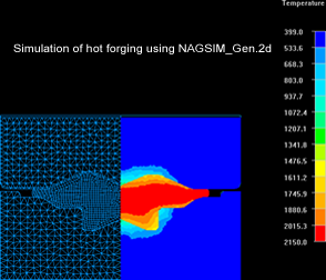
a forging progression automatically in minutes.The sequence designs
created in NagForge can be tested effortlessly in NAGSIM_Gen.2D
FEA simulation software.
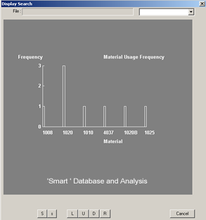
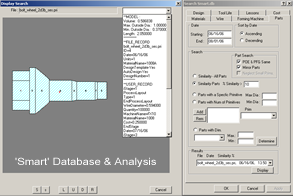
In addition to sequence design,
NagForge has a 'Smart' database and analysis module to store 'Knowledge'
and use it to improve the design and manufacturing processes.
Uses:
- Search its 'Smart' database to find
similar parts and the knowledge available including sequence
designs, lessons learnt, tool life etc. Prevent reinventing
sequence design or spending hours to design a wrong forging
sequence.
- Create hot forging part profile from
machined part profile.
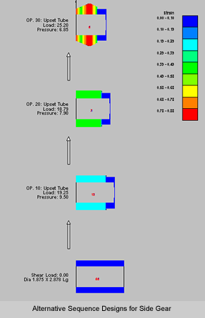
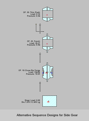
- Obtain alternative sequence designs
for forging a part in a few minutes.
- Calculate flash dimensions for closed
die forgings.
- Calculate die angle for Chevron free
extrusion.
- Create reusable sequence-design templates
of your own designs or designs from NagForge. Use these templates
to 'Zip through' progression design for similar 'Family of Parts'.
- Automate and standardize sequence design
of similar parts.
- Create DXF output of sequence designs
in a few minutes
- Select optimal blank diameter
- Reduce number of forming operations
- Obtain estimated loads, pressures and
deformation
- Estimate load distribution on a multi-station
machine
- Prevent designs that overload the tooling
or overstrain the part
- Teach forming design to new personnel
Limitations:
- NagForge is not a FEA simulation program.
It can not predict metal-flow defects and stress distribution
in tools.
- Nagforge can be used only for parts
with some symmetry such as parts made on upsetters, closed die
forgings with and without flash, ring rolling and open die forging
of symmetrical and long parts. Parts can have features such
as polygons, flats and splines.
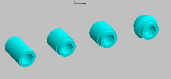
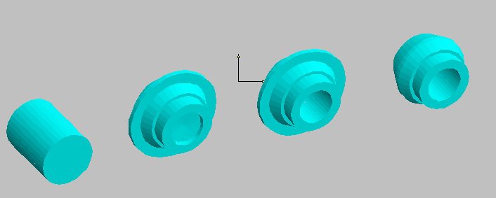
Alternative Forming
Progressions in Minutes
In general, there is more than one forming sequence by which a part
can be formed. The number of designs depends upon the constraints
such as part geometry, material being forged, allowed number of
operations, wire / rod size etc. NagForge has its own design logic
to determine various possible ways a part can be formed. Because
the program looks for all possible designs and applies its logic
without fail, NagForge can come up with design concepts that even
experienced designers may overlook.
Design by Command
'Design by Command' feature allows the user to create his/her own
design interactively in a few minutes. The interactive session,
consisting of questions by the program to determine design intent
and the responses of the user, is saved in a session file. This
session file can be used as a template to create progression design
for similar 'Family of Parts' in minutes.
Objectives of NagForge
'Smart' Database and Analysis Module
- Create and maintain a historic database
of parts designed, quoted and manufactured.
- Capture and retain the knowledge gained
from experience.
- Improve sequence design, quoting and
manufacturing processes.
- Eliminate duplication of effort.
- Reduce print-to-part time.
Search and Analysis
Capabilities - 'Smart' Database Module
- Part: Search for similar parts, parts
with certain features such as hex, lobe etc, parts within specified
length, diameter and volume.
- Design : Existing Auto or Manual designs
for current or similar parts.
- Material - usage.
- Wire /Rod size - usage.
- Forming Machine - usage
- Tool Life - for similar parts
- Cost - quoted and manufacturing.
- Lessons learnt on similar parts.
Template' Designs for
'Similar Parts' or 'Family of Parts'
For any part that is similar to a template in the database, NagForge
can follow the template design / session file to create forming
progression in minutes.
Manual Design
In addition to automatic design, NagForge has a separate module
for creating a forming progression manually. Using computer aided
techniques, the user can quickly construct a forming sequence according
to his/her own concept. The designer can also start from a computer-generated
design and modify it.
DXF Input and Output
In NagForge, a part is constructed using simple shapes called primitives.
The geometry of parts can also be imported from CAD systems such
as AutoCad, SolidEdge etc. The NagForge output including sequence
designs can be saved in DXF format for input to other CAD systems.
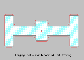
Forging Profile from
Machined Part Drawing
Nagforge has a separate module for creating Forging Profile from
machined part drawing. User can specify machining allowance on outside
profile as well as bore. Fillet and corner radii as well as forging
draft angles can be specified.
Automatic Creation of
Analysis File for NAGSIM.2D
For some of the sequence designs, NagForge can create the analysis
file for simulation of the sequence designs in NAGSIM.2D. For new
parts, for which tooling designs are not available, this saves considerable
effort required to create process drawings for FEA simulation.